
ENGINE ROOM -NANNI KUBOTA WATER PUMP REPLACEMENT – CUTLESS BEARING – SHAFT, PROPELLER & RUDDER TRIAL – NEW TILLER
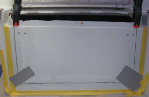
At the beginning of the refit we decided that we needed access to the stern. Therefore, we cut widely through the lazaret door. That was of a great help since it allowed us to undertake all the replacements in this confined space.

After fitting the wind vane bracket on the stern, it was time to repair the area and make sure that the lazaret will be totally watertight again. To this end, we used a few layers of woven roving on the inside and epoxy resin added with silica to fill up the external voids. Notice on the photo the clamps and duck tape which are used to hold the “door” in place during the bonding process.
Back to the engine room things were looking more promising every day. The surrounding area was covered with insulating material.

To insulate the engine room from the noise, we mainly used polyethylene closed cell foam of 15mm thick. This material is very convenient and can be glued on the GRP with a good quality neoprene adhesive. However, the sides of the engine and the cover board were insulated with a different type of insulation. We ordered special engine room soundproof panels made of bitumen sheets incorporated in between two layers of soft foam and covered with aluminium film.

The engine could finally be reinstalled.

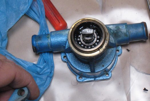
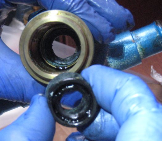
One of the last routine jobs was to replace the impeller. Yet, that turned out to be more complicated than expected. After extracting the old impeller, we discovered that the rings sealing the oil from the water had also to be replaced. That meant: dismantling the whole Johnson water pump.

That wasn’t a so easy. Firstly, we had to extract the pump from the engine block and then drive the shaft out to access the seals.

A small bracket with three nuts and tooth lock washers holds the pump on the main engine block. An extra o-ring seals the pump itself to prevent any oil leak.
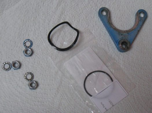
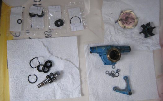
The little shaft was pushed out with the help of a wooden block and a plastic mallet. Finally, the two seals and a plastic spacer were driven out. This little spacer, which can be identified on the picture below, keeps the two seals away from each other and therefore prevents any ingress of water in the oil system.

On the shaft itself, two ball bearings are fixed and lubricated from the engine oil. We could have changed those as well, but there were still in perfect condition. All other parts of the pump were changed and the pump was finally re-installed on the main engine block.
To install the new Vetus water-lock, we had to try many positions. The issue with this piece of equipment is that it needs to be placed at a certain height and distance from the engine. The exhaust elbow should be above the water-lock and a minimum distance of 30cm must separate the elbow from the water lock. For such a small engine room that was a bit of a problem.

We tried to be as accurate as possible keeping the throttle cables free and the water-lock fixed in place with some plastic stripes. By the end, the position of the water-lock wasn’t very satisfactory due to the lack of space in the engine room. This position could eventually be modified.


Removing the old cutless bearing was a bit challenging and had to be done as gently as possible, to avoid any damage to the stern tube. The new one, ordered from J.Rogers Boat Yard, needed some adjustment . The basic theory with cutless bearings involves an interference fitting in between the stern tube and the bearing itself. This fitting means a tiny difference which can only be obtained after very precise measurements. In other words, the bronze part of the cutless bearing had to be reduced on a milling machine. We ended up with an interference fitting of 0.2mm. The tube was then forced into the stern tube with a rubber mallet.

The shaft and propeller could then be introduced into the stern tube. Our new shaft was ordered slightly longer to keep a margin in case of error. Of course we knew that at some point the excess will have to be chopped off.
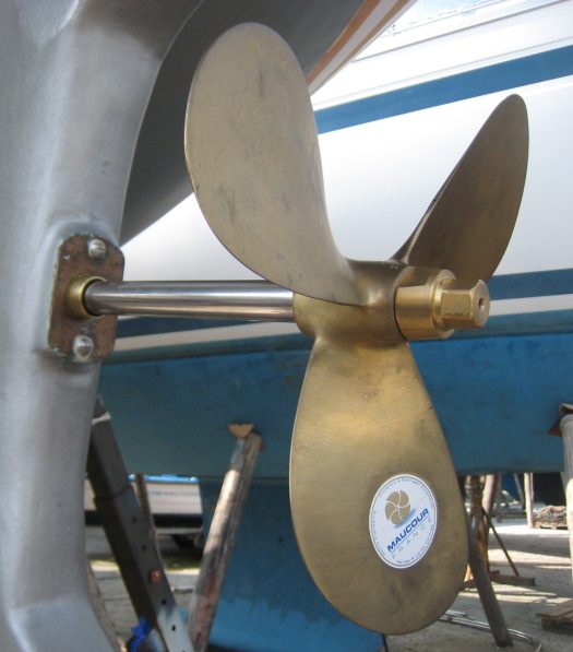
This was firstly done with a small hack saw and finished with a cutting disc. A small amount of electrical tape was used to mark the circumference around the shaft and to ensure a perfect round cut.


Thankfully, the rudder was in good condition and totally dry. We applied an anti-osmotic treatment as it was previously done on all the hull.

Firstly a few coats of International Gelshield Plus.

Then a couple of coats of International Gelshield 200, which dries very quickly.


On the Contessa 32 the rudder shaft has three bronze bearings. One is in the cockpit, where the tiller is connected. The second bearing is situated under the water line where the rudder starts and the last bronze ring is at the heel plate. We replaced all three of them and made sure they were fitting perfectly.
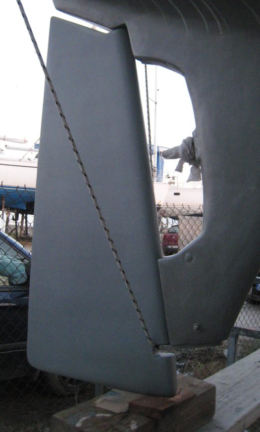
We did a trial on how the rudder fitted into those bearings, checking for any extra adjustments to ensure a smooth helming.

Another part ordered from J. Rogers was the new tiller. Our old tiller had two cracks at the base and we decided to buy a new one. As we discovered comparing the two tillers, the old one had been shortened by the previous owner leading us to the conclusion that at some point the tiller had been damaged.

A very fine piece of craftsmanship. This unique tiller was varnished with 8 coats of Epifanes Gloss Finish. The 4 first coats were thinned with the adequate Epifanes thinner and after each coat, we sanded with 400 grade sandpaper.


I got what you mean , thankyou for posting.
LikeLiked by 1 person
Good blog you have got here.. It’s difficult to find quality writing like yours these days. I honestly appreciate people like you! Take care!!
LikeLiked by 1 person