

ENGINE ROOM REFIT – WATER TANK – PLUMBING – MAINSHEET TRAVELLER – PACIFIC WINDPILOT
The engine room refurbishment was obviously a major task this month. We were waiting for ages to be able to use epoxy resin. Since December, the temperatures were below anything acceptable. First thing in the plan: bonding the two thick plywood pieces which would increase the width of the engine beds.
Prior to bonding, the two ply pieces (25mm) were treated with a coat of pure resin. This coat would seal the wood and provide a better contact surface during the next step.
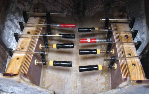
The pieces were then glued to the engine beds with a mix of resin and colloidal silica. Edges were smoothed with fillets and clamps were left in place for at least 2 days. A heater was also necessary to warm up the area for the first 8 hours.
Eventually, the old screw holes were filled with the same mix.
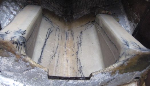
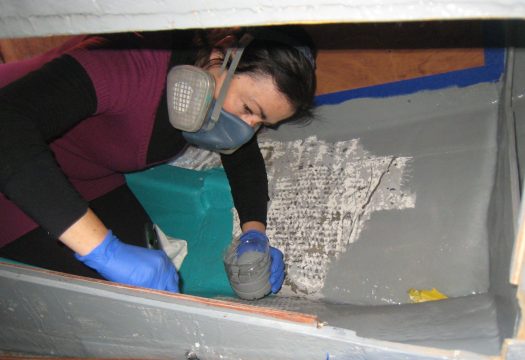
After the epoxy had cured, we cleaned the area with warm water and a Scotch Brite pad. This step is crucial during cold temperature works in order to get rid of amine blush: an epoxy by-product often appearing in cold/humid conditions. The area was later thoroughly sanded by hand with 80-grit sandpaper. To re-enforce the whole new structure, fibreglass cloths would be added. The laminating process happened in two steps:
-Firstly, the various cloths were cut into shape (Twill Weave, Woven Roving & Biaxial cloth)
-Secondly, the cloths were laminated to the structure
Few remarks are important to be underlined here. After some readings, we understood that above 200 gr, the fibreglass cloths would not bend nicely on the corners. Therefore, those had to be smoothed by sanding. The other important point was to calculate the number of cloths needed to obtain the desired thickness. In theory a 165 gr Twill Weave would give more or less 0.15mm thickness and a 200 gr Woven Roving would give approximately 0.25mm. A layer of 300gr biaxial cloth was also added in between the other layers. In total, on each side of the engine beds, we laminated 10 layers of fibreglass cloths obtaining roughly 3mm to 4mm thickness. All those numbers can be found through readings, but those are theoretical. In practice, the thickness obtained depends on the quantity of resin used and how well the cloths are applied. It is also very important to step each sheet to avoid building any hard spots.

All fibreglass cloths were applied in one session to consolidate the chemical bonds. We used fast curing hardener (West System 205) specially formulated for cold bonding works and the temperature was kept in between 16°C and 22°C. Everything went well and a layer of Peel Ply was added at the end to get a nice finish and protect the area from amine blush.

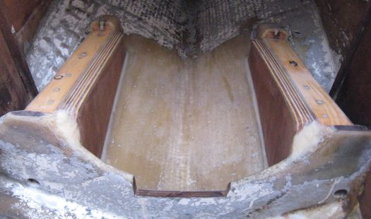
After a couple of days curing, the Peel Ply was pulled away. This is probably the most pleasant moment when you finally uncover your work. The black stains remained on the laminate are due to the marker used to draw the sheets. After washing the area again with warm water and a Scotch Brite, it was sanded and recovered with a couple of coats of pure resin.
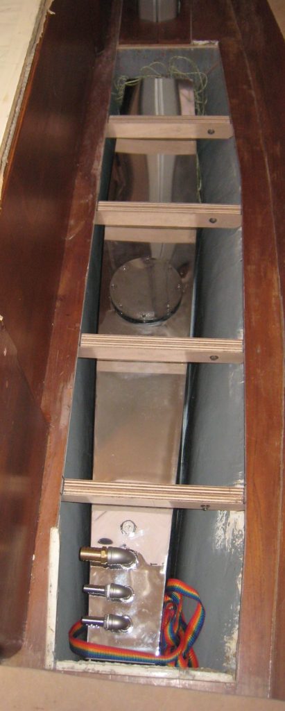
The engine could now be placed on the beds and aligned with the shaft.
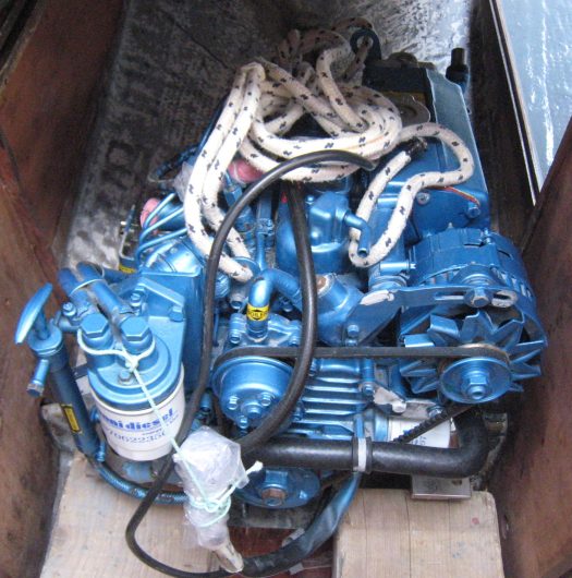
Alignement is a long process which can quickly become nerve racking. But with a bit of goodwill and a lot of patience we finally did it. The first step was to align roughly the engine on the beds. Finding the lateral position was the most difficult part mainly because of the flexibility of the engine mounts. The vertical position was much easier to get. Due to the confined space it took us a few hours of unpleasant contorsions.

After extracting again the engine, we could finally drill the holes for the 8 lag screws. Instead of putting the engine in and out, we could have used the template we had, but we were afraid of doing any mistake with the drilling. Anyway, with a bit of practice, taking the engine in and out became quite fluent !
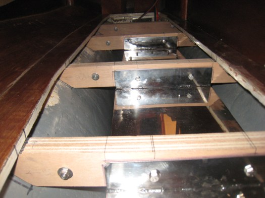
On each side of the engine beds, 4 stainless steel lag screws were inserted leaving exactly 12 mm above for the stainless steel plates(10mm) and the washers (2mm). Using a slide gauge is also a common practice in this kind of drilling. On the other hand and because of the reduction of the engine bed height, it was necessary to find the right screw length and to drill at the right depth. For 10 mm lag screws, the laminate and the encapsulated wood below was drilled to 8mm, not less, not more.
The epoxied areas were then treated with a two part epoxy paint.

Lastly, Danboline bilge paint was applied on a warm day. It must be noted that this one really stinks. Using a proper mask is not a luxury.
Now the engine room was ready for the next phase.

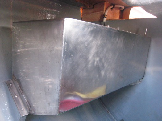
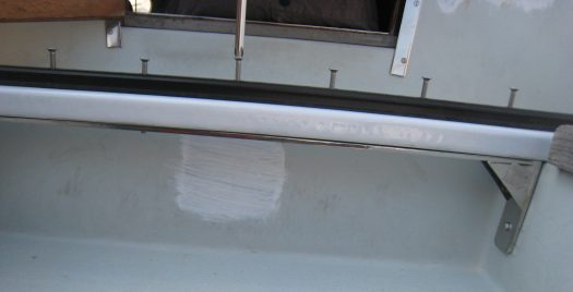
Apart from the engine room project, we had to resume our plumbing installation. We did get our new stainless steel water tank which could now be installed in the bilges. It was a great moment of satisfaction when the tank perfectly fitted above the keel. 85 litres of nice clean water and an extra ballast of about 110 kilos were very welcome.
The floor mounts were also coated with epoxy resin to make them water resistant.

Each floor mount was then through bolted to the tank with a couple of 6mm stainless steel studs. This will ensure the stability of the tank at sea.
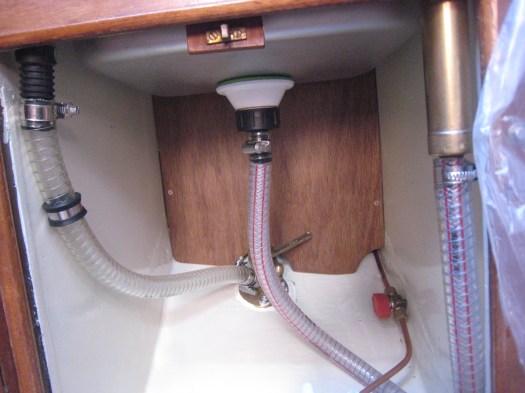
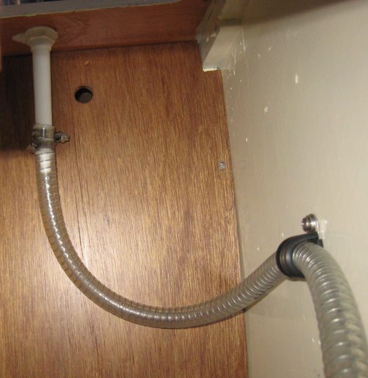
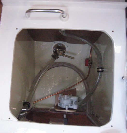
Hoses for water inlet and the galley supply were finally fitted.


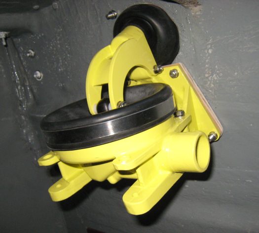
At the galley, a hose was connected from the tank to the foot pump and from this to the faucet. The sink was connected to the brass hand pump and then to the seacock through a non return valve.
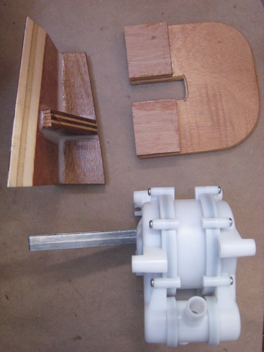
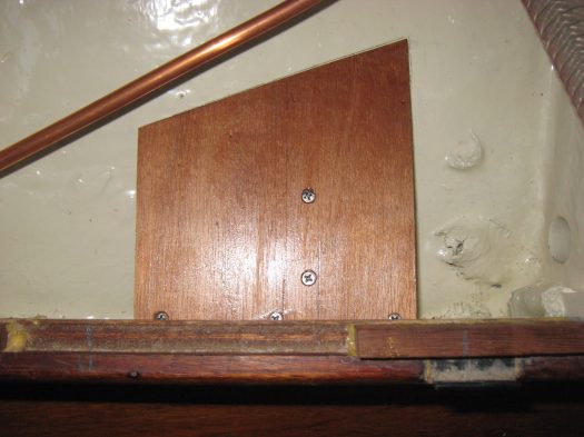
To install the Whale foot pump we had to create a small floor for the pump to be fixed. This was done with some plywood offcuts and epoxy resin. The pump was then through bolted to those plywood pieces.

For the whole installation, we used proper steel wire re-enforced marine hoses and stainless steel jubilee clips.

Notice that no electrical device had been added to this installation. On such a small plumbing circuit it is probably a waste of energy. The Whale foot pump is effective enough and providing an economical water consumption.
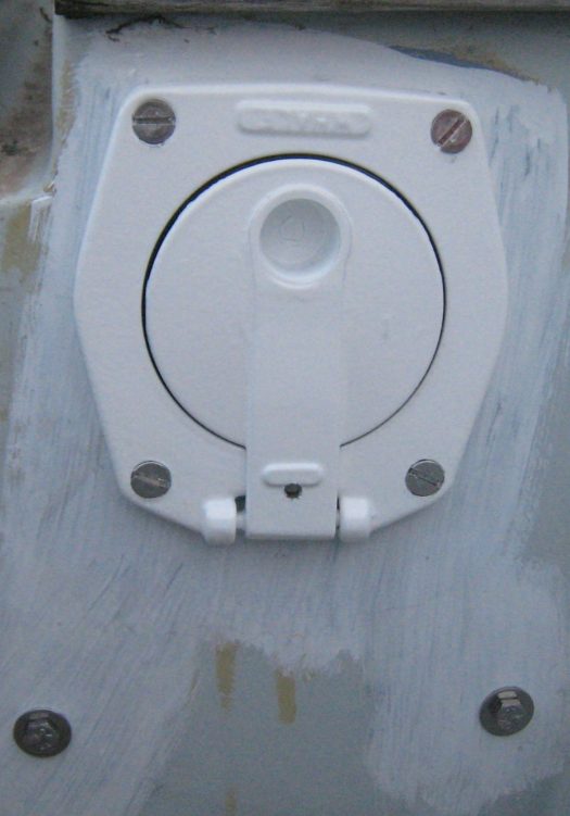
In the cockpit locker a manual bilge pump was added. The Whale Gusher 10 is one of the toughest models on the market. It is made of alloy and is easy to service. Not a cheap piece of equipment though, but when talking about pumping water out of the boat fast, it is always better to be on the safe side: 65 litres/minute. Having used this pump on other boats, we were convinced of its efficiency.
The pump was mounted in the locker, but an optional deck plate was added in order to avoid opening the locker. The deck plate was fixed on the port side next to the companionway. This permits to empty the bilges without having to get out in the cockpit.
Our old diesel tank was thouroughly cleaned inside out and polished.

Bringing it back into its original place was not an easy job. We confirm that it can go in and out from the cockpit locker, without any major problems.
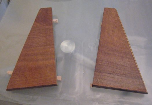
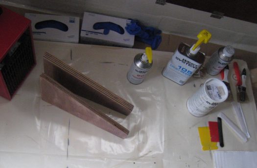
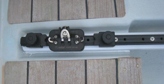
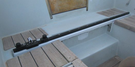
The mainsheet traveller installation was another job we accomplished this month. We created two pieces to ensure extra support for our new Antal gear. After a long search on the subject, we found out that replacing the old IYE track was not an easy matter. As we are not planning to race a lot, we wanted to keep it as simple as possible. The latest tracks are complicate and often look like aérospatial pieces of gear. Nevertheless, we could not afford the Harken solution and didn’t fancy much the Lewmar design. Therefore, Antal was ideal for us combining simplicity, an ergonomic design and a very efficient ball bearing system.
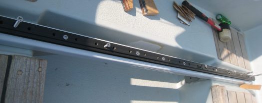
To add some stiffness to the installation we constructed a plywood piece supporting the track. It was wrapped in fibreglass cloths and resin. Under the track, you can notice a heavy piece of stainless steel “bridge”making the construction strong enough to endure the mainsheet pulling forces.
At the moment everything is kept simple. But if needed in the future, we can always add some cam-cleats to the traveller.
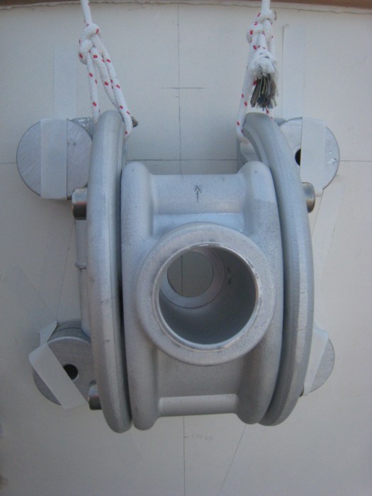
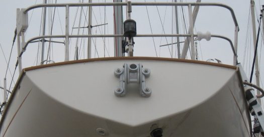
Windpilot: one of the best piece of gear on the boat. We are still looking for a name, but we just fitted the main bracket. Here again, after a long search on the subject and quite a bit of reading, we followed some of the other Contessa’s owner advices. We choose to buy a brand new Pacific Windpilot for several reasons. Firstly, it is one of the lighter vane available on the market. We also had the chance to meet the man who owns the company and sells this magnificent piece of technology. We realised that Peter Förthmann is probably the best expert on the subject. Based on the servo-pendulum principle, the Pacific Windvane is very strong and has proved to be very well suited for Contessa’s: it is light, compact, easy to install and has already been fitted on many other CO32. We are looking forward to try it under sail.
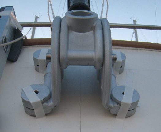
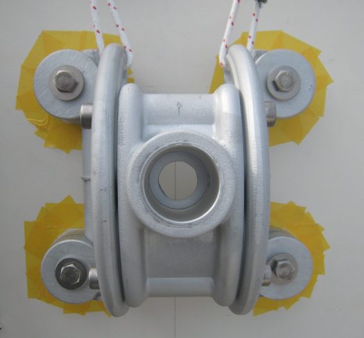
The main difficulty when fitting the bracket to the transom, is to find the center of the boat. After that, you need to calculate the maximum height were you can drill the holes. In other words, you have to calculate the taffrail thickness, the deck thickness and allow 1 or 2 cm for the washers to fit nicely under the hull and deck joint. Measuring correctly the height of the holes can be done from inside the lazaret taking into account the deck thickness. After that, you first drill a thing hole (4mm) and if you are happy with the height, you can open up the hole with a thicker drill. In general, when drilling crucial holes we always increase the drill thickness step by step. When the 10.5mm hole is done, you pass a first bolt to hold the bracket in place and then you can mark the next holes. The rest of the job consists of drilling 3 other holes of 10.5 mm through the boat. When buying the gear, you will receive a very well documented manual explaining everything in detail.
At last, the bracket was put into place with Bostik marine construction adhesive. By the way, because you are using stainless steel bolts (A4) on an Alloy bracket, it is always better to use Duralac or Lanolin to prevent electrolysis in between the different metals.

très impressionnée par votre dernier post! Bravo aussi pour les informations que vous fournissez.
LikeLiked by 1 person
Salut les travailleurs!! Ouah super boulot une fois de plus, bravo👏👍 Je suis dans les travaux aussi. J’ai enfin pu démarrer après les grosses gelées de l’hiver! Je suis dans les vannes Blake en ce moment, je vous enverrai quelques photos, je devrais également terminer les barres franches la semaine prochaine (j’en ai collé 2 du coup!). J’ai une petite question: vous avez remplacé les vannes par des neuves, qu’avez vous fait des anciennes? Je serais intéressé pour récupérer les contre-écrous car il en manque sur les miennes…😟😟 Donc si vous jetez vos vieilles vannes dites le moi je pourrais les récupérer …😉 Bon courage les marins!! Laurent
Envoyé de mon iPad
>
LikeLiked by 1 person
Absolutely pent subject material, appreciate it for entropy.
LikeLike
Great postt thank you
LikeLike